
Custom Controller
My degree is in Electrical Engineering, so anytime I can control something with electronics, I will. For the reef tank I decided to go with a Raspberry PI/Arduino Mega setup. The Arduino will handle controlling all of the relays and monitoring float switches. I’ll probably have at least a temperature probe on it just as a backup to the dedicated temperature controller.
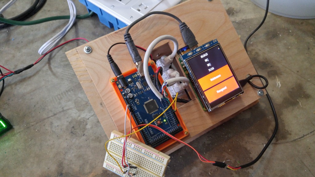
The PI is running a simple Python script that has buttons on a touchscreen to turn pumps on/off for maintenance. It will also have the lighting schedule. It then sends the commands over to the Arduino for triggering the relays. Some of the pumps will also be directly controlled by the Arduino using the float switches, such as the water top-off.
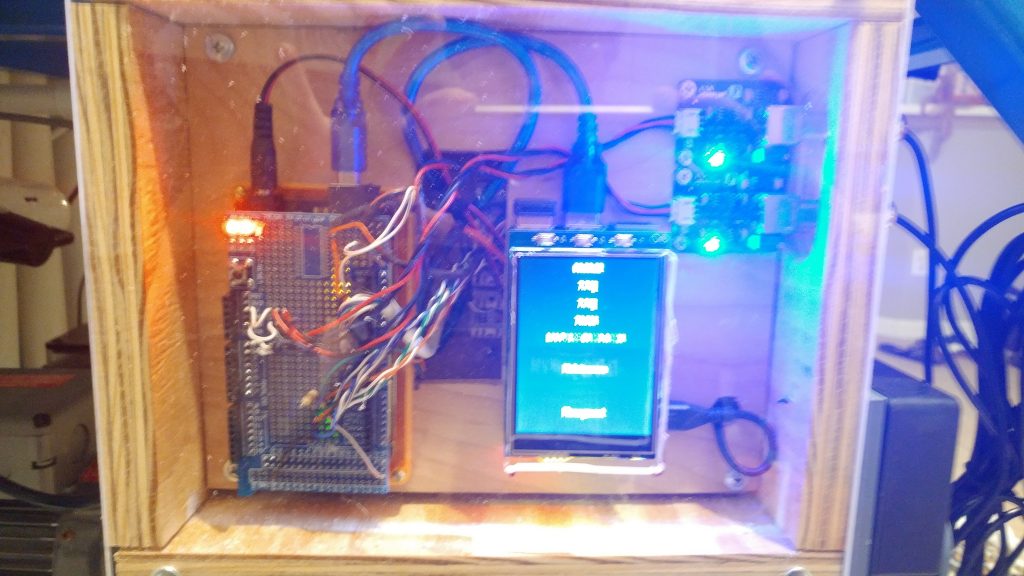
Here’s the controller box during the build process. All of the IO is going through RJ45 connectors in the back of the box. The front of the box will have plexi so you can see all the LED’s flashing. There will also be a cutout so that you can get to the touch screen on the Pi.
Inputs
There are 7 inputs into the controller.
- 1 Temperature
- 2 pH
- 5 Float switches
Temperature
My initial plan was to use dedicated Temperature and pH controllers, but after some quick searching, I decided to let the Arduino handle these duties as well. I had a spare DS18B20 1-wire temperature probe laying around, so I did some quick programming and had the system working in no time.
pH
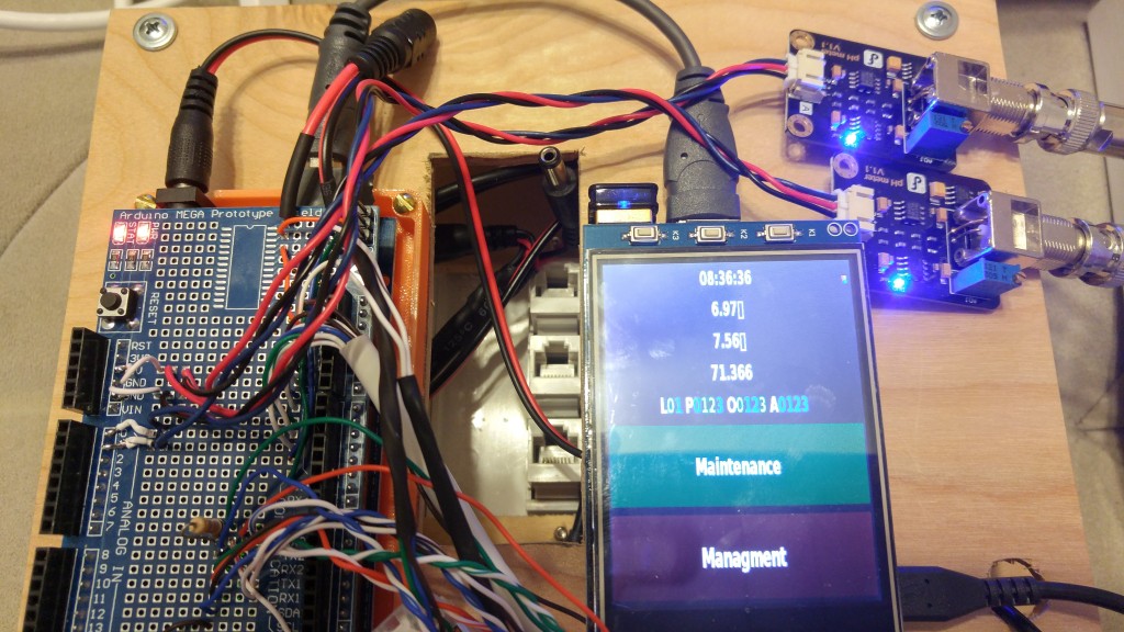
The pH is monitored by a pair of pH probes bought from DFRobot.com . After calibrating, they appear to be pretty accurate and consistent. I decided to mount the circuits on the front so I can see the power LEDs and verify they are working at a glance.
I had to write a custom python script that I can login to the Pi and run for the calibration. I then store the calibration information in memory on the arduino itself.
You can also see that at this point I have added an IO shield to the Arduino to solder all of the connectors to. All I have left at this point is to finish buttoning up the box and the controller is in a useable state.
Float Switches
The Arduino has float switches for High-Water scenarios for the sump, tank, and skimmer cup. In the event any of those three go High, the associated pump will be turned off and an email will be sent to me. The pump will stay off until I manually turn it back on on the Pi.
There are two Low-Water float switches, one for the sump and one for the water Top-Off. The sump switch will be used to pump top-off water into the sump. The Low-Water switch in the top-off tank is used to alert me when more water needs to be added.
Outputs
There are 10 outputs on the controller. Each output can source 5 Amps total.
- 3 Pump relays (Return, Recirculation, Top-off)
- 1 Heater relay
- 1 Chiller relay
- 1 Fan Relay
- 1 Oceans Motions Relay
- 3 Light Relays (2 daylight, 1 reverse-daylight)
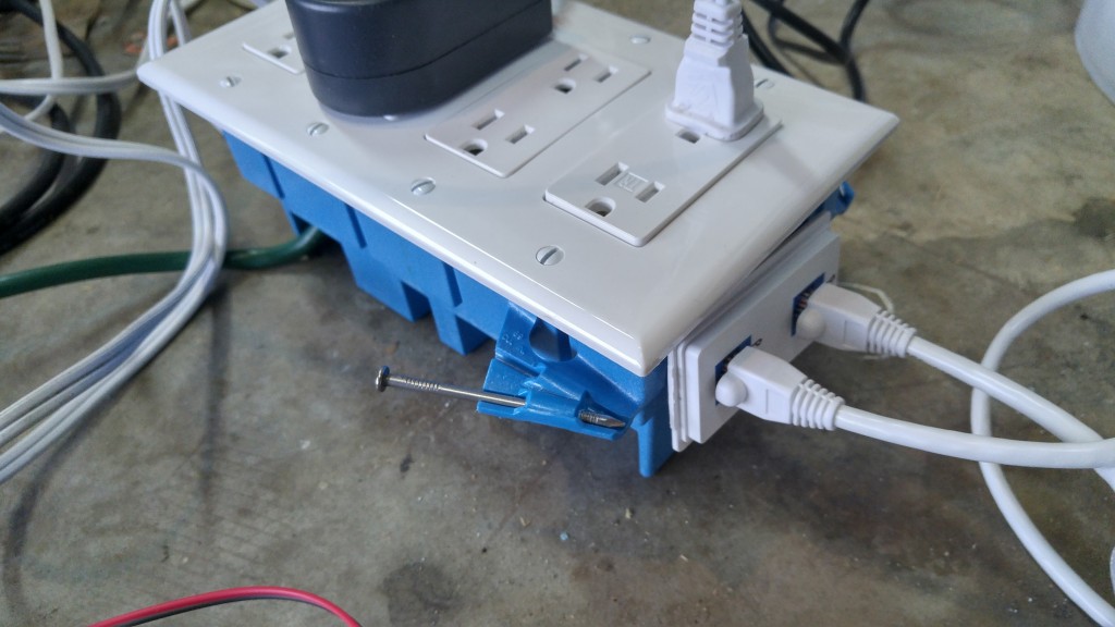
Here’s a close up of the Relay box that I built. I found that the Sainsmart 8-channel relay board would fit in the bottom of the industrial size 4-gange outlet box. Some quick work with a hacksaw and I was able to mount the RJ45 connectors to the side of the box for the inputs. Each outlet is on it’s own separate circuit so that they can be controlled independently. The outlet box will be mounted in the top center of the stand so that all the power cables can easily reach it.
Get The Code
If you’ve read this far, then you must be pretty interested in my setup. I created a github so that I can track changes as I make them to the code. The Code is currently set to Private while I finish working through a few things. I’ll make it public at some point.
https://github.com/niget2002/AquaControl
The Pi Image is being stored as a shared Google File
https://drive.google.com/open?id=0B168py-wpZVeQkdhazNpV1p0VE0